If you are looking for the Chapter 12 content for the 2nd Edition of Exploring Arduino, please click here.
Hardware and Timer Interrupts
Parts List
- Arduino Uno
- A-B USB Cable
- Pushbutton
- Piezo Buzzer
- Common Cathode RGB LED
- 10kΩ Resistor
- 100Ω Resistor
- 150Ω Resistor
- 220Ω Resistors (x3)
- 10uF Electrolytic Capacitor
- 74AHCT14 Hex Inverting Schmitt Trigger
- Jumper Wires
- Breadboard
Code
Download Code (1st Edition, Chapter 12)
(Also available on GitHub)
Useful Links
- Arduino attachInterrupt() Function Reference
- Arduino Timer1 Library Download
- 74AHCT14 Datasheet (PDF)
Errata
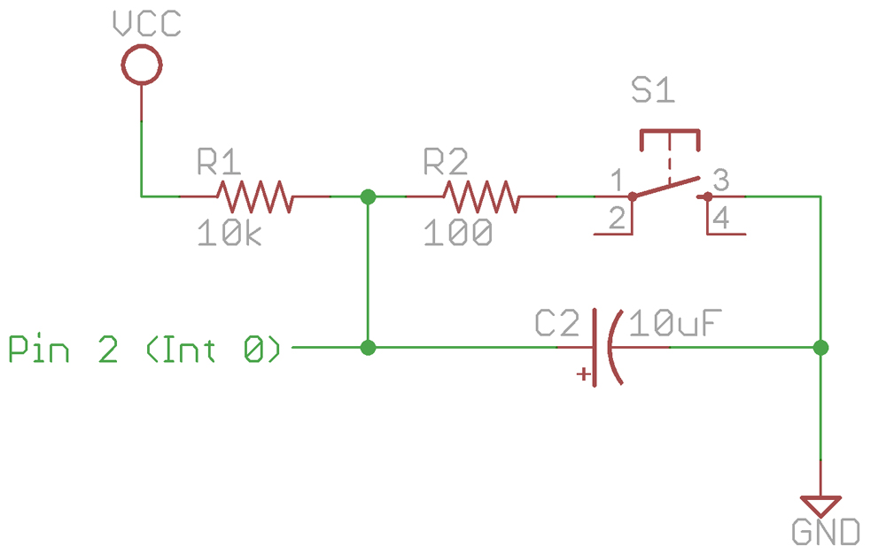
- The text description of 12-3 on page 264 incorrectly says that the “resistor decreases the discharge time.” It should say that the “resistor increases the discharge time.”
- Figures 12-3 and 12-6 (the hardware debouncing schematics) don’t match up exactly with the wiring diagrams shown in figures 12-8 and 12-9. The original schematics show the 10k pullup resistor connected at the junction of the 100ohm resistor and capacitor. The wiring diagrams, on the other hand, show the 10k pullup resistor connected at the junction of the 100ohm resistor and the pushbutton. The circuit will work the same either way, but for consistency, you can find an updated version of the schematics that matches the wiring diagram and demo video here:
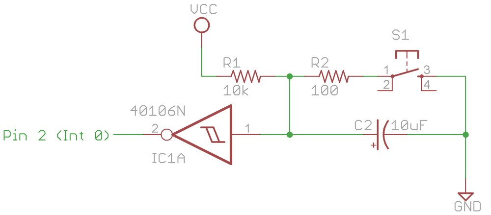
- On page 265, the explanation of hysteresis could be more clear. This is a better one:
Most microcontrollers are already designed to handle slowly rising or falling digital input voltages. When looking at the datasheet of the ATMega microcontroller, for example, you’ll find that the input pin low and high voltage thresholds are different. When an input signal is transitioning from high to low, it must drop below 0.2Vcc to register as a logic high. When an input signal is going from low to high, it must rise above 0.7Vcc to be registered as a logic high. Vcc represents the supply voltage of the chip (5V in our setup). This gap ensures that the value does not flutter during the transition step, and is called hysteresis. To observe this effect directly (before sending your signal to the microcontroller), you can utilize a Schmitt Trigger in your circuit.
Color Wiring Diagrams

Chapter 12, Figure 8

Chapter 12, Figure 9
Videos
Follow along with this video tutorial about external interrupts and hardware debouncing:
Watch a demo of the hardware-interrupted Arduino with button debouncing created in the chapter:
Watch a demo of the “Sound machine” created in the chapter: